
Deep Dive into Flexible PCB Impedance Failures and Yield Recovery Strategies
In today's era of high-frequency, high-speed smart hardware, even micron-level deviations can cause flawless circuit designs to fail during mass production. Many engineers face this frustrating scenario: simulations in the design phase appear perfectly aligned, yet the delivered products on the production line...flexible PCB(Flexible Printed Circuit, or FPC)flexible PCBHowever, during Time Domain Reflectometry (TDR) testing, frequent impedance "Fail" results were encountered, putting the entire batch of boards at risk of scrapping.
Impedance control failure not only leads to significant material waste but also directly hampers subsequent processes.flexible PCBAProduction progress for (flexible circuit board assembly).
To help you permanently solve this quality challenge, our technical team has released a white paper titled "Root Cause Analysis and Process Optimization for High-Speed FPC Impedance Control Failures."
1. Tracing the Root Cause: The 4 Culprits Behind FPC Impedance Failures
In this promotional report, based on detailed metallographic cross-section analysis of thousands of real-world cases, we have identified the core root causes of flexible circuit impedance deviations from standard ranges (such as common high-speed differential 90Ω/100Ω drops or exceedances):
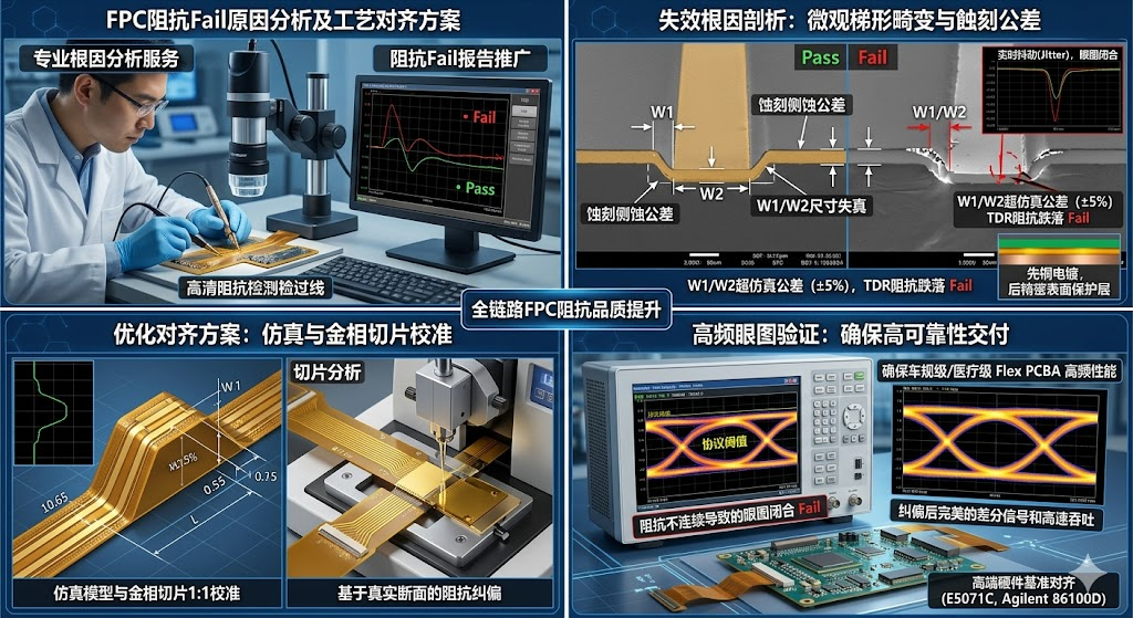
1. Etching tolerance and trapezoidal distortion of the micro cross-section
Flexible circuits are prone to undercut or over-etching during etching due to the extremely thin substrate. This can cause actual line width/spacing (W1/W2) dimensions to exceed the predefined golden tolerance of the simulation (e.g.,$\pm5\%$When this occurs, the distributed capacitance changes abruptly, causing the TDR impedance curve to deviate from the central reference line.
2. Electroplating sequence process and uneven microcrystalline structure
Precision plating processes are the foundation of impedance continuity. The report provides an in-depth analysis of micro-void connectivity in plating cross-sections. Strict control is essential during surface treatment and micro-cross-section management.Copper electroplating first, followed by precision surface tin (or gold) protective layerThe cross-sectional layer sequence. If the layering is disordered or copper thickness is uneven, high-frequency currents under the skin effect will cause additional signal dispersion, disrupting the originally continuous characteristic impedance.
3. Flow and non-uniformity of dielectric layer during cover film lamination
During high-temperature and high-pressure lamination, uncontrolled adhesive flow (excess squeeze-out) can intrude into the differential line spacing (S). Because the adhesive has a vastly different dielectric constant (Er) compared to air and the PI substrate, even minor fluctuations in the dielectric layer manifest as a distinct impedance dip on the TDR monitoring curve.
4. Stiffener compression deformation
where precision component placement is requiredflexible PCBARigid support areas, or localized stress relief inconsistencies caused by FR4 or stainless steel reinforcement during lamination, can also alter parasitic capacitance and create risks for high-frequency signal reflections.
II. Precision Diagnosis: Full-Link Impedance Correction and Optimization Solutions
When facing impedance failures, blindly tweaking parameters only traps you in a reactive cycle of fixing one issue at the cost of another. This whitepaper details a closed-loop correction workflow that spans from simulation to production line validation.
Simulation model calibration: Move beyond simplistic theoretical formulas. Fully integrate a numerical solver logic compliant with the Polar Si9000e industry standard. Precisely parameterize real-world cross-sectional trapezoidal angles, resin flow deformation, and surface protection layer thicknesses (copper first, then tin) to ensure simulation accuracy matches physical measurements.
Premium Hardware Baseline Alignment: By comparing high-precision metallographic micro-sectioning with TDR impedance-controlled line measurements, we calibrate and align lab test data against industry-leading hardware such as E5071C or Agilent 86100D. This ensures precise capture of real-time jitter, eye diagram closure, and microscopic impedance discontinuities, detecting every physical defect exceeding protocol thresholds.
Process window freeze: Instruct the production line to strictly lock in vacuum lamination temperature profiles, electroplating current density, and precision etching compensation tolerances, ensuring impedance fluctuations are contained within specifications from the source.
3. Smart Manufacturing Assurance: Empowering High-Reliability Delivery
Superior quality stems from reverence for data and relentless craftsmanship. From high-density multi-layerflexible PCBFrom optimized impedance tolerance to one-stop premium qualityflexible PCBAFor precision SMT processing, we not only deliver highly insightful and persuasive Failure Analysis (FA) reports but also directly translate these findings into measurable yield improvements on your production line.
Reject impedance failure. Ensure every high-end flexible hardware product achieves flawless high-speed eye diagrams and rock-solid transmission quality!
Welcome to click/contact us for free accessComplete Version: "In-depth Analysis Report on FPC Impedance Failure and Quality Correction Guide"Help your hardware R&D avoid detours!